If a posterior tooth has been lost and is not restored immediately, the patient may subsequently experience a variety of problems. The adjacent teeth tend to tilt and rotate, and the opposing tooth may overerupt. Available options to restore occlusion include elective root canal treatment with invasive tooth reduction, surgical impaction or orthodontic therapy requiring extraoral headgear or full-arch braces to reinforce anchorage.1-4 Unfortunately, these treatments may be inconvenient and they are not always as effective as desired, since the loss of anchorage is always evident. To avoid lengthy and unpredictable treatment, many restorative dentists prefer to perform elective root canal treatment followed by aggressive tooth reduction to restore the occlusal plane. However, the advent of titanium mini-screws has enabled orthodontists to use the skeletal anchorage to overcome these problems.5-11
Skeletal anchorage involves placing temporary orthodontic anchorage devices, in the form of mini-screws, into the bone and using them for absolute anchorage.12,13 Of the various implants available, temporary anchorage devices are widely used because they are relatively simple to insert, and force can be applied almost immediately.14 Other advantages include fewer limitations at the implant site, no need for patient compliance and lower cost than other types of implant. Temporary anchorage devices are used for a variety of purposes in orthodontics, including space closure, treatment of an open bite and uprighting of the posterior teeth.2-4,10,12,13,15
This case report describes a minimally invasive clinical procedure for intrusion of 2 maxillary molars using 4 temporary orthodontic anchorage devices.
Case Report
A 44-year-old woman was referred from the restorative department of the King Abdulaziz University (Jeddah, Saudi Arabia) for intrusion of the maxillary molars to facilitate restoration of the lower first molars (Fig. 1).
The patient's dental history included loss of the lower left first molar, which had resulted in overeruption of the opposing upper first molar. In addition, her lower right first molar was severely damaged, which had led to overeruption of the upper right first molar. The lower right second molar and left first molar were also missing. The upper right second premolar had been subjected to prior root canal therapy, but the result was defective and nonrestorable, and the tooth was therefore indicated for extraction (Fig. 2).
Lateral cephalometric analyses showed that the patient had a Class I skeletal relationship with an acceptable profile (Fig. 3, Table 1). The right and left canines were in a Class I relationship, the overbite was 40% and the overjet was 3–4 mm (Fig. 4).
At the time of referral, the patient was scheduled for prosthetic full-crown coverage of the lower right first molar, as well as placement of an endosseous dental implant and crown to replace the missing upper right second premolar and lower right first molar.
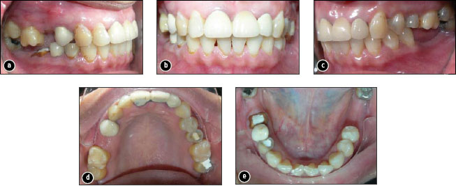
Figure 1: Initial intraoral photographs: a) view of the right side, showing overeruption of the first molar; b) frontal view; c) view of the left side, showing overeruption of the first molar; d) occlusal view of the upper arch; e) occlusal view of the lower arch.
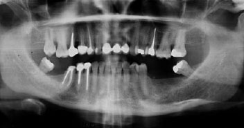 Figure 2: Panoramic radiograph showing multiple root canal treatments and multiple missing teeth. |
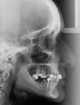 Figure 3: Lateral cephalograph showing a Class I skeletal relationship with an acceptable profile. |
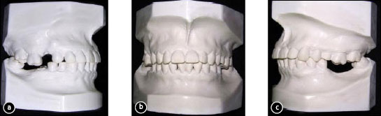
Figure 4: Pretreatment study casts: a) view of the right side, showing the amount of overeruption of the first molar; b) frontal view; c) view of the left side, showing the amount of overeruption of the first molar.
Table 1 Cephalometric measurements of the patient described in this case
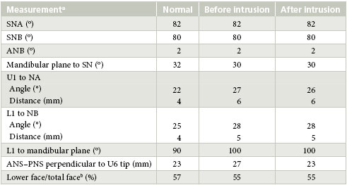
aS = sella, N = nasion, A = point A, B = point B, U1 = upper incisor, L1 = lower incisor, U6 = upper first molar, ANS = anterior nasal spine, PNS = posterior nasal spine. bCalculated as (ANS – Gn)/(N – Gn) × 100, where Gn = Gnathion.
Treatment Plan and Progress
It was decided to undertake intrusion of the upper right and left first molars using 4 temporary orthodontic anchorage devices to facilitate restorative treatment of the lower right and left molars. Four temporary anchorage devices, 6 mm in length and 1.6 mm in diameter with long transgingival part, were used (OrthoEasy system Forestadent, Pforzheim, Germany). Two of the devices were placed between the upper right first and second molars on the buccal side and mesial to the upper first molar on the palatal side. The other 2 devices were placed between the upper right first molar and second premolar on the buccal side and between the first molar and the second premolar on the palatal side. These positions were chosen to facilitate the required intrusive movement. One operator (KHZ) placed all of the devices.
About 0.5 mL of local anesthetic (2% xylocaine with 1:100 000 epinephrine) was administered by infiltration before placement of the temporary anchorage devices. Buttons (Rocky Mountain Orthodontics Inc, Denver, CO) were bonded to the buccal and palatal surfaces of the upper first molars (Fig. 5). The temporary anchorage devices were immediately loaded with 100 g of intrusive force using a closed elastic power chain (Rocky Mountain Orthodontics Inc). The power chain was activated every 2 weeks. After 3 months, the upper left buccal device was partially covered with an overgrowth of soft tissue; at this point, 0.012-in. ligature wires were engaged to the device and bent to make a hook over which the power chain could be attached (Fig. 5b).

Figure 5: Intraoral photographs showing the palatal and buccal mini-screws used to intrude both the right and the left first molars: a) right first molar intrusion using a temporary anchorage device and force delivered with a power chain attached to a button bonded to the buccal surface of the tooth; b) left temporary anchorage device with power chain attached to a button bonded to the buccal surface of the molar; 0.012-in ligature wires were engaged to the device and bent to make a hook over which the power chain could be attached; c) view of the right and left temporary anchorage devices with power chains attached to buttons bonded to the palatal surfaces of both molars.
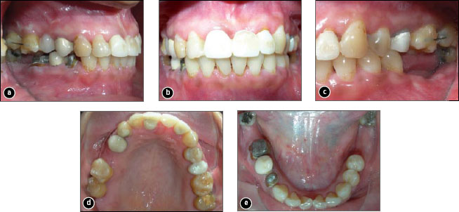
Figure 6: Final intraoral photographs: a) view of the right side, showing the fixed retention wire between the first and second molars; b) frontal view with provisional temporary crowns in place; c) view of the left side, showing the fixed retention wire between the first and second molars; d) occlusal view of the upper arch; e) occlusal view of the lower arch.
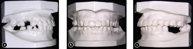
Figure 7: The final study casts: a) right side view, showing the amount of intrusion achieved to the first molar; b) frontal view; c) view of the left side, showing the amount of intrusion achieved to the first molar.
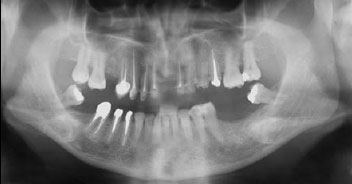 Figure 8: Post-treatment panoramic radiograph. |
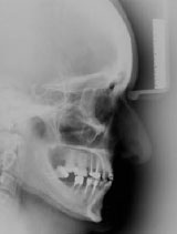 Figure 9: Post-treatment lateral cephalograph. |
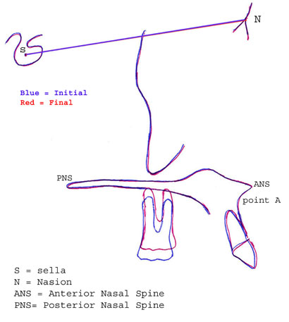
Figure 10: Superimposition showing molar intrusion of 4 mm.
After 6 months of orthodontic treatment with the 4 upper temporary orthodontic anchorage devices, functional occlusion was established in the right and left posterior dentition through 4-mm intrusion of the upper first molars (Fig. 6, Table 1). This created adequate space to restore the opposing edentulous spaces (Fig. 7 and 8). For retention, a 0.018-in. stainless steel wire was bonded to the buccal surfaces of the intruded teeth to the second molars on both sides (Fig. 6a and 6c).
Discussion
For the patient described in this case, successful orthodontic intrusion was achieved but this would not have been possible without the use of temporary anchorage devices as a means of absolute anchorage. Furthermore, using these devices prevented the potential adverse effects of conventional orthodontics, such as extrusion of adjacent teeth.
There is no agreement in the literature on the optimum force to be used for intrusion. Some authors suggest forces ranging from 15 to 50 g,16-18 whereas others have recommended using greater force for intrusion (150 to 500 g).10,19,20 Andreasen and Bishara21 suggested using 40% more than the optimal force when the elastic is first applied, to compensate for the loss of force that occurs at the outset. Therefore, the clinicians in the case reported here started with a force of 100 g, knowing that 40% of this force would be lost within the first 24 hours. The power chain was activated bimonthly to maintain constant application of force.
One technique for performing this intrusion, which has been used by a number of clinicians, is to pull the power chain from one temporary anchorage device to the other across the occlusal plane. However, this method has several drawbacks, including tearing, slippage of the power chain over the occlusal surface and lack of proper control to direct the forces through the centre of resistance. Therefore, in this case the power chains were run from each temporary anchorage device to bonded buttons to control the intrusive force. Another advantage of the method used here was that only the extruded teeth were bonded with attachments. Furthermore, the position of the bonded buttons played an important role in directing the force through the centre of resistance, thus producing the required bodily movement. Radiographic examination revealed that the quality of bone distal to the first molar was insufficient on the upper left side; therefore the temporary anchorage device was placed mesial to the first molar. Placing both devices mesially would have resulted in uneven intrusion of the first molar (i.e., more mesial). For that reason, the buttons were bonded to the distal half of the palatal surface to help direct the force through the centre of resistance of the tooth.
Temporary anchorage devices have significant advantages; however, their placement is technique-sensitive and carries some risks. Potential complications include root injuries, loss of tooth vitality, osteosclerosis and dentoalveolar ankylosis.22,23 Furthermore, there is a chance that the nerve will be injured during placement in the maxillary palatal slope, where the greater palatine foramen is located.24,25
Cephalometric superimposition registered on the palatal plane (between the anterior and posterior nasal spines), which was used to compare the initial and final cephalographs, showed that the first molars had been intruded by 4 mm in 6 months (Figs. 9 and 10, Table 1).
Conclusions
This case demonstrated that substantial intrusion of the maxillary molars could be achieved in a well-controlled manner by using only temporary anchorage devices without fixed orthodontic appliances to create adequate vertical clearance for restorations. With these devices, well-controlled force (in terms of both direction and magnitude) can be obtained for successful orthodontic intrusion of the molars.
THE AUTHORS
|
|
Dr. Al-Fraidi is a postgraduate orthodontic resident at the Ministry of Health, Madina, Saudi Arabia. |
|
Dr. Zawawi is assistant professor and head of the orthodontic division, faculty of dentistry, King Abdulaziz University, Saudi Arabia. |
Correspondence to: Dr. Khalid H. Zawawi, Orthodontic division, Faculty of dentistry, King Abdulaziz University, P.O. Box 80209, Jeddah 21589, Saudi Arabia. Email: kzawawi@kau.edu.sa
Acknowledgement: The authors would like to acknowledge an orthodontic icon, the late Professor Anthony A. Gianelly.
The authors have no declared financial interests in any company manufacturing the types of products mentioned in this article.
This article has been peer reviewed.
References
- Schoeman R, Subramanian L. The use of orthognathic surgery to facilitate implant placement: a case report. Int J Oral Maxillofac Implants. 1996;11(5):682-4.
- Daly PF, Pitsillis A, Nicolopoulos C. Occlusal reconstruction of a collapsed bite by orthodontic treatment, pre-prosthetic surgery and implant supported prostheses. A case report. SADJ. 2001;56(6):278-82.
- Yao CC, Wu CB, Wu HY, Kok SH, Chang HF, Chen YJ. Intrusion of the overerupted upper left first and second molars by mini-implants with partial-fixed orthodontic appliances: a case report. Angle Orthod. 2004;74(4):550-7.
- Yao CC, Lee JJ, Chen HY, Chang ZC, Chang HF, Chen YJ. Maxillary molar intrusion with fixed appliances and mini-implant anchorage studied in three dimensions. Angle Orthod. 2005;75(5):754-60.
- Chenin DA, Trosien AH, Fong PF, Miller RA, Lee RS. Orthodontic treatment with a series of removable appliances. J Am Dent Assoc. 2003;134(9):1232-9. Erratum in: J Am Dent Assoc. 2003;134(10):1322.
- Costa A, Raffainl M, Melsen B. Miniscrews as orthodontic anchorage: a preliminary report. Int J Adult Orthodon Orthognath Surg. 1998;13(3):201-9.
- Gray JB, Smith R. Transitional implants for orthodontic anchorage. J Clin Orthod. 2000;34(11):659-66.
- Kanomi R. Mini-implant for orthodontic anchorage. J Clin Orthod. 1997;31(11):763-7.
- Maino BG, Bednar J, Pagin P, Mura P. The spider screw for skeletal anchorage. J Clin Orthod. 2003;37(2):90-7.
- Umemori M, Sugawara J, Mitani H, Nagasaka H, Kawamura H. Skeletal anchorage system for open-bite correction. Am J Orthod Dentofacial Orthop. 1999;115(2):166-74.
- Gray JB, Steen ME, King GJ, Clark AE. Studies on the efficacy of implants as orthodontic anchorage. Am J Orthod. 1983;83(4):311-7.
- Roberts WE, Nelson CL, Goodacre CJ. Rigid implant anchorage to close a mandibular first molar extraction site. J Clin Orthod. 1994;28(12):693-704.
- Shellhart WC, Moawad M, Lake P. Case report: implants as anchorage for molar uprighting and intrusion. Angle Orthod. 1996;66(3):169-72.
- Melsen B, Costa A. Immediate loading of implants used for orthodontic anchorage. Clin Orthod Res. 2000;3(1):23-8.
- Maino BG, Maino G, Mura P. Spider Screw: skeletal anchorage system. Prog Orthod. 2005;6(1):70-81.
- Burstone CR. Deep overbite correction by intrusion. Am J Orthod. 1977;72(1):1-22.
- Gianelly AA, Goldman HM. Biologic basis of orthodontics. Philadelphia (PA): Lea & Febiger; 1971.
- Melsen B, Fiorelli G. Upper molar intrusion. J Clin Orthod. 1996;30(2):91-6.
- Park YC, Lee SY, Kim DH, Jee SH. Intrusion of posterior teeth using mini-screw implants. Am J Orthod Dentofacial Orthop. 2003;123(6):690-4.
- Paik CH, Woo YJ, Boyd RL. Treatment of an adult patient with vertical maxillary excess using miniscrew fixation. J Clin Orthod. 2003;37(8):423-8.
- Andreasen GF, Bishara S. Comparison of alastik chains with elastics involved with intra-arch molar to molar forces. Angle Orthod. 1970(3):151-8.
- Asscherickx K, Vannet BV, Wehrbein H, Sabzevar MM. Root repair after injury from mini-screw. Clin Oral Implants Res. 2005;16(5):575-8.
- Mine K, Kanno Z, Muramoto T, Soma K. Occlusal forces promote periodontal healing of transplanted teeth and prevent dentoalveolar ankylosis: an experimental study in rats. Angle Orthod. 2005;75(4):637-44.
- Sujatha N, Manjunath KY, Balasubramanyam V. Variations of the location of the greater palatine foramina in dry human skulls. Indian J Dent Res. 2005;16(3):99-102.
- Wang TM, Kuo KJ, Shih C, Ho LL, Liu JC. Assessment of the relative locations of the greater palatine foramen in adult Chinese skulls. Acta Anat (Basel). 1988;132(3):182-6.
Correction
Reference 5 was missing from the reference list when this article was originally published in JCDA Volume 76, Issue 1. This reference has now been added to the online version. JCDA regrets the error.