
Abstract
Background: The inferior alveolar nerve courses anteriorly within the mandibular canal, providing sensory nerve supply to the mandibular teeth, the buccal mucosa, the gingiva, and the soft tissues of the lower lip and chin. To avoid damage to this nerve and resulting sensory disturbances, its exact location must be known before placement of a dental implant. Imaging modalities currently used to visualize the position of the inferior alveolar nerve may be inaccurate. This study was undertaken to determine the accuracy of micro–computed tomography (micro-CT) for determining the position of this nerve.
Methods: Micro-CT images of 16 cadaveric hemimandibles were acquired at a slice thickness of 154 µm. Each hemimandible was then sectioned at 6 predetermined locations between the ramus and the mental foramen, to yield 5 corticocancellous bone specimens. The superior, inferior, buccal and lingual distances for bone surrounding the mandibular canal were measured by direct digital caliper and compared with corresponding micro-CT measurements obtained by 3-dimensional visualization and modelling software.
Results: There was substantial variability in the vertical position of the inferior alveolar nerve, depending on the length of time since tooth loss and the movement of the nerve from the lingual to buccal position as it courses from the posterior to the anterior aspect of the mandible. However, digital caliper and corresponding micro-CT measurements of the thickness of bone surrounding the inferior alveolar nerve were highly consistent, and no significant differences were detected between the two methods of measurement.
Clinical Significance: The findings reported here confirm the accuracy of micro-CT in determining the location of the inferior alveolar nerve during planning for placement of dental implants in the human mandible.
Accurately determining the exact location of the inferior alveolar nerve as it courses through the body of the mandible is imperative, to avoid neurosensory disturbances secondary to implant placement.1,2 Previous studies have examined the position of this nerve relative to the alveolar ridge, the inferior border of the mandible, or the buccal and lingual margins of the mandible.3-5 Variability in the vertical position of the inferior alveolar nerve has been reported.3,4 More specifically, one study showed a high degree of variability in the distance between the centre of the mandibular canal and the superior border of the alveolar ridge.4 In contrast, descriptions of the nerve’s pathway from the lingual to the buccal aspect of the mandible, as it passes anteriorly from the molar region to the mental foramen, are relatively consistent.3,4
Radiography and computed tomography (CT) are currently used to visualize critical structures near the proposed site of any dental implant.1, 6-8 To select the appropriate dimensions for an implant, clinicians must be able to accurately measure the distance between the superior border of the mandibular canal and the superior border of the mandible, as well as the mandibular width at the superior border of the mandible.8 The results of previous studies examining the accuracy of radiography suggest that key landmarks, such as the mental foramen, may not be clearly visible.1,7 The results of studies examining the accuracy of CT have been mixed.5,9
Following the loss of a tooth, the resulting bone remodelling and resorption can lead to a loss in alveolar bone height and width.10 In fact, the extent of bone remodelling and resorption is directly correlated with the length of the edentulous period following extraction of a posterior mandibular tooth. The results of a previous study suggested that the reduction in bone height between the alveolar ridge and the mandibular canal is the most striking characteristic of mandibular atrophy.4
The current study was conducted to determine the accuracy of micro-CT imaging in precisely locating the inferior alveolar nerve and to provide a landmark for older, edentulous patients who are candidates for the surgical placement of dental implants.
Methods
Eight right-sided and 8 left-sided hemimandibular human cadaver specimens fixed in formalin were examined using micro-CT scanning technology. Three of the specimens were from women, 5 were from men, and 8 were from people of undetermined sex. The age range was 65 to 90 years. Of the 16 hemimandibular specimens, 4 were edentulous, 11 were partially edentulous, and 1 had a full set of teeth.
Micro-CT imaging was performed with a multi-slice micro-CT scanner (GE Locus Ultra, GE Healthcare, London, ON) at the Robarts Research Institute in London, Ontario. Images were obtained at settings of 120 kV, 20 mA, 16-second exposure time and slice thickness 154 µm. Isotropic voxel dimensions were 154 µm in each of the x, y and z directions. Three-dimensional (3D) visualization, measurement and modelling software (Amira 4.1, Visualization Sciences Group (VSG), Burlington, MA) was used to import the micro-CT data files. After imaging, a padded table vice was used to support and position each hemimandible while it was being cross-sectioned at 6 predefined locations across the mandible, to yield 5 dentoalveolar specimens. The first proximal cross-section was performed at the junction between the anterior aspect of the coronoid process of the ramus and the posterior body of the mandible. Horizontal and vertical distance measurements were obtained with reference to this junction point on each hemimandible, to ensure that the measurement used in the digital measurement software was obtained at the same location on the cadaveric specimen. Each section of bone was associated with a predefined width measurement, corresponding to a particular tooth (Table 1, Fig. 1). A protractor was used to ensure that the plane of each section formed a right angle with the inferior border of the hemimandible, to allow for standardization between edentulous and partially edentulous hemimandibles, as well as the single dentate hemimandible. Individual sections were assigned a numeric value of 1 through 5, from the third molar to the first premolar, respectively (Fig. 1).
Usig a digital caliper, 2 independent observers measured, in random order, the thickness of the mandibular bone surrounding the mandibular canal in each of the 5 dentoalveolar specimens for each hemimandible, as described below. Two weeks later, each observer repeated these measurements. The superior, inferior, buccal and lingual distances for bone surrounding the mandibular canal were measured from the posterior aspect of each of the 5 sections for each hemimandible (Fig. 2). To ensure consistency between the observers in the superior distance measurement, a mandibular profile classification scheme was devised to categorize the superior profile as bimodal, conical or dentate (Fig. 2). For each bimodal section, the superior distance (SD) was measured from the most superior aspect of the mandibular canal to the lowest aspect of the alveolar ridge (Fig. 2). For the conical and dentate sections, the superior distance was measured from the most superior aspect of the mandibular canal to the highest aspect of the alveolar ridge (Fig. 2). For all sections, the inferior distance (ID) was measured from the most inferior aspect of the mandibular canal to the most basal aspect of the mandible (Fig. 2). The buccal distance (BD) was measured from the most lateral aspect of the mandibular canal to the buccal margin, and the lingual distance (LD) was measured from the most medial aspect of the mandibular canal to the lingual margin (Fig. 2). Bone distance measurements were manually recorded in a spreadsheet.
 Figure 1: Sections 1 to 5 for hemimandible 8L (the eighth left hemimandible). The location of the neurovascular bundle can be visualized on the posterior surfaces of sections 4 and 5.
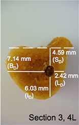
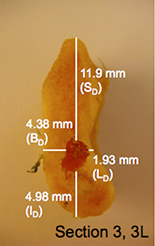

Figure 2: Mandibular profile classifications (bimodal, conical or dentate) and the 4 bone measurements obtained using a digital caliper: superior (SD), inferior (ID), buccal (BD) and lingual (LD) (observer 1, observation 1). 2L, 3L and 4L = second, third and fourth sections from left hemimandible.
For each of the 16 specimens, a file conforming with the Digital Imaging and Communications in Medicine (DICOM) standard and containing all relevant information was created and stored using the Amira 4.1 software. Each DICOM file contained 3D image data of the specified hemimandible (i.e., a series of parallel 2-dimensional image slices across a 3D volume). In addition, a 3D isosurface image, representing the original hemimandible from which the data were derived, was obtained from each data set. The software assigns colour to an isosurface based on CT attenuation of the bone. In this case, an optimized range was determined and used for all DICOM file sets representing each hemimandible, to enable visualization of mandibular surfaces and consistentcy across all specimens.
Table 1 Predefined bone width measurements for sections 1 to 5
| Section | Corresponding tooth | Width of section (cm) |
| 1 | Third molar | 0.5 |
| 2 | Second molar | 1 |
| 3 | First molar | 1 |
| 4 | Second premolar | 0.75 |
| 5 | First premolar | 0.75 |
After scanning, the hemimandibles were cut using a Stryker saw (Stryker Model 810 Autopsy Saw, Azusa, CA). The sectioning performed, and bone measurements obtained, during the dissection stage of the study were then reproduced digitally in the 3D model. This process enabled direct comparison between measurements obtained with the digital calipers on the physical model and measurements obtained by digital means on the 3D model. To ensure that the cutting planes selected during the dissection stage of the study was reproduced in the 3D modelling software, the same horizontal and vertical distance measurements used to ascertain the virtual cutting plane. Successive predefined width measurements, intended for use as virtual markers, were obtained anteriorly along the body of the mandible. These markers were separated by 1-mm distances accounting for the thickness of the Stryker saw blade (Table 1, Fig. 3, Panel A).
To replicate the sectioning performed with the Stryker saw, 5 orthogonal slices were created in the coronal plane of the mandible (Fig. 3, Panel B), which allowed the user to extract and view specific slices from the 3D data set. To replicate the locations where cuts had been made with the Stryker saw, each orthogonal slice was then repositioned at the posterior aspect of each of the premeasured sections of bone (Fig. 3, Panel B). The user could thus extract a slice from the 3D data set, at the exact location from which bone measurements surrounding the mandibular canal had been taken during the dissection stage of the study (Fig. 3, Panels C and D).
For each of the 5 sections from each hemimandible, the protocol developed for measurement with the manual digital caliper was also used for the micro-CT bone distance measurements (Fig. 3, Panels C and D) using the software’s 3D ruler. Specimens were classified as bimodal, conical or dentate (Fig. 4), and the superior, inferior, buccal and lingual distances of the bone surrounding the canal were measured (to 2 decimal places) in the coronal plane. The order of measurement was randomized, and measurement was performed on 2 occasions, separated by a 2-week interval, by 2 independent observers. Data were analyzed by means of SPSS 17.0 statistical software (SPSS Inc., Chicago, Illinois). Intraclass correlation coefficients were calculated to assess intra-observer and inter-observer measurement reliability and to assess the consistency between digital caliper and micro-CT measurements. Because intraclass correlation was high, means and standard deviations were calculated for all measurements by both observers for sections 1 through 5, as determined by digital caliper and by micro-CT.
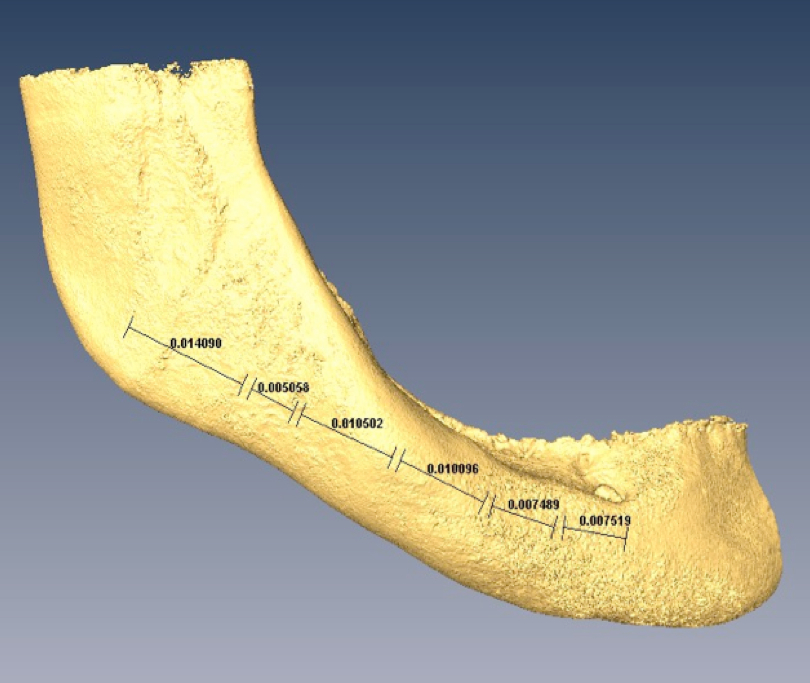


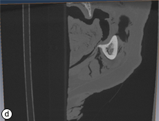
Figure 3: Method used by modelling software to reproduce sectioning and bone distance measurements obtained during the dissection stage of the study

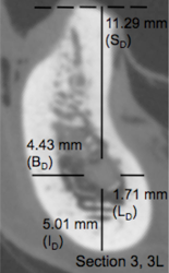
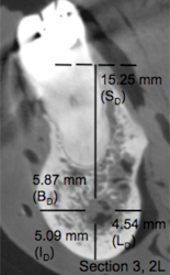
Figure 4: Mandibular profile classifications (bimodal, conical or dentate) and the 4 bone measurements determined from micro–computed tomography images: superior (SD), inferior (ID), buccal (BD) and lingual (LD) (observer 1, observation 1). 2L, 3L and 4L = second, third and fourth sections from left hemimandible.
Univariate analysis of variance (ANOVA) was performed for all measurements to determine if the mean of any distance (SD, ID, BD and LD) for any section (1 through 5) as measured with the digital caliper was significantly different from the corresponding mean distance as measured with micro-CT. A second ANOVA was carried out for superior distance measurements only to determine if the mean superior distance for sections 1 through 5 classified as bimodal, conical or dentate, as measured with the digital caliper, was significantly different from the corresponding mean superior distance as measured with micro-CT. For each ANOVA, the measurements of the 2 observers were combined.
Results
All distance measurements showed high intraobserver and inter-observer agreement for each modality. The intraclass correlation coefficients for digital caliper bone distance measurements were 0.99 while interaclass correlation coefficents for micro-CT bone distance measurements was 0.90. This indicates that both observers could reliably measure the position of the nerve in both modalities. The interclass correlation coefficient values for digital caliper and micro-CT bone distance measurements were 0.92. This indicates that the digital and cadaveric measures were consistent and valid. In addition, the measurements obtained by digital caliper were highly consistent with the corresponding micro-CT measurements demonstrating the precise anatomical relationship of the inferior alveolar nerve as it courses anteriorly through the trabecular bone of the mandible from the lingual to buccal aspect. (Table 2)
To demonstrate the usefulness of the mandibular profile classification system, superior bone distance measurements were subdivided according to classification (bimodal, conical or dentate) and the section (1 to 5) from which they were taken (Table 3). The robustness and consistency of the digital approach is highlighted by a high interclass correlation between modalities coupled with the understanding that a variety of diverse mandibular profiles were included in the measurement regime. Also, the precise anatomical relationship of the inferior alveolar nerve is well described within the mandible coursing from the lingual to buccal aspect of the mandible as it passes from the posterior to anterior direction. However, some caution should be exercised in drawing conclusions from these data, given the small sample sizes for some sections. It is recommended that future studies use a similar classification system to further explain the variability in superior distance measurements.
Table 2 Mean mandibular bone distance measurements (in millimetres) obtained by digital caliper and micro–computed tomography (micro-CT)*
| Superior distance | Inferior distance | Buccal distance | Lingual distance | |||||
|---|---|---|---|---|---|---|---|---|
| Section | Caliper | Micro-CT | Caliper | Micro-CT | Caliper | Micro-CT | Caliper | Micro-CT |
| 1 | 11.79 (2.70) | 11.01 (4.34) | 10.23 (3.39) | 9.03 (3.37) | 3.43 (1.49) | 3.33 (1.56) | 2.47 (1.15) | 3.13 (1.60) |
| 2 | 12.96 (3.42) | 11.72 (3.80) | 7.47 (1.90) | 7.39 (2.15) | 4.71 (1.62) | 4.33 (1.42) | 2.82 (1.28) | 3.28 (1.64) |
| 3 | 12.99 (4.42) | 11.83 (4.42) | 6.60 (1.75) | 6.16 (1.82) | 5.74 (1.13) | 6.12 (1.07) | 2.47 (1.27) | 2.79 (1.35) |
| 4 | 14.0 (5.16) | 13.77 (4.37) | 7.58 (1.65) | 7.48 (1.57) | 4.62 (1.32) | 5.40 (1.20) | 2.56 (1.30) | 2.80 (1.29) |
| 5 | 15.08 (5.00) | 14.42 (4.57) | 9.10 (1.66) | 8.90 (1.25) | 3.43 (1.14) | 3.63 (0.80) | 3.02 (1.39) | 3.93 (2.20) |
*Data are presented as mean with standard deviation in parentheses (n = 16). ANOVA analysis indicated no measures were significantly different p>0.05.
Table 3 Mean bone superior distance (in millimetres) obtained by digital caliper and micro–computed tomography (micro-CT) for each mandibular profile.*
| Bimodal | Conical | Dentate | ||||
| Section | Caliper | Micro-CT | Caliper | Micro-CT | Caliper | Micro-CT |
| 1 | 10.90 (2.55) n = 10 |
10.83 (3.18) n = 10 |
12.92 (2.55) n = 5 |
10.48 (6.52) n = 5 |
15.02† n = 1 |
15.50† n = 1 |
| 2 | 9.25 (3.33) n = 5 |
7.73 (2.97) n = 5 |
14.13 (2.10) n = 6 |
12.83 (2.93) n = 6 |
15.25 (1.23) n = 5 |
14.37 (2.10) n = 5 |
| 3 | 5.73 (2.06) n = 3 |
4.34(3.09) n = 3 |
12.78 (1.52) n = 8 |
12.61 (2.02) n = 8 |
17.68 (0.48) n = 5 |
15.07 (2.24) n = 5 |
| 4 | 2.49† n = 1 |
2.00† n = 1 |
12.36 (3.70) n = 9 |
12.84 (2.73) n = 9 |
18.37 (1.96) n = 6 |
17.11 (1.68) n = 6 |
| 5 | 6.42† n = 2 |
5.76† n = 2 |
12.81 (4.37) n = 4 |
13.50 (2.63) n = 4 |
17.72 (1.83) n = 10 |
16.52 (2.08) n = 10 |
*Data are presented as mean with standard deviation in parentheses.
†Standard deviation not available because n< 3.
For the first ANOVA, conducted with all distance measurements, no significant differences were detected in relation to technology (digital caliper vs. micro-CT) or specific distance measurement (SD vs. ID vs. BD vs. LD) (p > 0.05) (Table 2). Likewise, for the second ANOVA, conducted with the superior distance measurements only, no significant differences were detected in relation to technology (digital caliper vs. micro-CT) or classification (bimodal vs. conical vs. dentate) (p > 0.05) (Table 3).
Discussion
A comparison of micro-CT measurements of the superior, inferior, buccal and lingual mandibular cortical distances of bone surrounding the mandibular canal in 16 dissected hemimandibles with manual measurements obtained by digital caliper demonstrated the accuracy of measurements obtained by imaging software.
The results of this study support the findings of a previous study reporting the high degree of accuracy of CT in visualizing the amount of bone surrounding the mandibular canal.5 In that earlier study, distance measurements for bone surrounding the mandibular canal obtained by CT were compared with measurements obtained using a digital caliper for a total of 6 cadaveric hemimandible specimens.5 The present study used higher-resolution CT (micro-CT) and found that it was a useful imaging modality for preoperative planning of dental implant placement in the posterior mandible.
Potential confounding factors included the measuring instrumentation, the application of the measuring instrumentation by each observer, the length of time between observations, the method of selecting reference points for sectioning and measurements, and the small sample size, all of which might affect extrapolation of these findings to the general population.
One noteworthy aspect of the current study that is recommended for future studies using a similar design and a mixed sample of specimens was the classification of differently shaped sections of mandibular bone. Classification of the mandibular sections as bimodal, conical or dentate ensured greater consistency in superior distance measurements between observers and across multiple observations and helped to explain their variability.
It is also important that future studies using similar methodology ensure accuracy in selecting reference points for hemimandibular sectioning and for the measurements of superior, inferior, buccal and lingual distances from the inferior alveolar nerve. Such future studies could reduce potential inaccuracies during sectioning by placing extrinsic markers on the mandible, at 6 predefined locations along the lateral aspect of the mandible, before scanning.5 Placement of such markers would ensure that specimens are sectioned at the exact locations and angles indicated by the markers during the dissection stage of the study. This method would also ensure that the specimens are sectioned at the same 6 locations and angles by the modelling software.
Particular care should be taken in future studies to ensure consistency in the initial starting points selected for measurement of superior, inferior, buccal and lingual distances surrounding the mandibular canal. This will help to ensure measurement accuracy within and between observers. To ensure such accuracy between observers and across multiple observations in the present study, the most superior, inferior, buccal and lingual aspects of the mandibular canal were selected as the starting points for the respective measurements surrounding the canal.
Conclusions
To our knowledge, no other studies have assessed the accuracy of micro-CT imaging in determining the location of the inferior alveolar nerve. The findings of this study provide insight regarding baseline mandibular bone quantity in older adults with various degrees of edentulism. This study has confirmed the accuracy of micro-CT imaging software for measuring distances between the inferior alveolar nerve and the superior border, inferior border, and buccal and lingual surfaces of the mandible. Further studies are needed to confirm the potential benefit of micro-CT imaging between the anterior border of the coronoid process and the mental foramen in the planning of implant placement in edentulous and dentate mandibles.
THE AUTHORS
 |
Ms. Massey is a master’s in clinical anatomy graduate, department of anatomy and cell biology, Western University, and a registered nurse in Toronto, Ontario. |
 |
Dr. Galil is a dentistry professor, department of anatomy and cell biology, divisions of clinical anatomy, orthodontics, and periodontics, Schulich School of Medicine & Dentistry, London, Ontario. |
 |
Dr. Wilson is associate professor, department of anatomy and cell biology, division of clinical anatomy, and director of the Corps for Research of Instructional and Perceptual Technologies (CRIPT) lab, Schulich School of Medicine & Dentistry, London, Ontario. |
Acknowledgements: The authors thank Hailey Linklater in the Department of Anatomy and Cell Biology for her assistance in the gross anatomy laboratory. Thanks also to Joseph Umoh, at the Imaging Research Laboratories of the Robarts Research Institute for his expertise and operation of the micro-CT system. Funding for this research was provided through department start-up funds provided to one of the coauthors (T.D.W.).
Correspondence to: Timothy D. Wilson, The University of Western Ontario, Department of Anatomy and Cell Biology, 490 Medical Sciences Building, London, ON N6A 5C1. E-mail: tim.wilson@uwo.ca
The authors have no declared financial interests.
This article has been peer reviewed.
References
- Kieser J, Kieser D, Hauman T. The course and distribution of the inferior alveolar nerve in the edentulous mandible. J Craniofacial Surg. 2005;16(1):6-9.
- Wadu SG, Penhall B, Townsend GC. Morphological variability of the human inferior alveolar nerve. Clin. Anat. 1997;10(2):82-7.
- Gowgiel JM. The position and course of the mandibular canal. J Oral Implantol. 1992;18(4):383-5.
- Ulm CW, Solar P, Blahout R, Matejka M, Watzek G, Gruber H. Location of the mandibular canal within the atrophic mandible. Br J Oral Maxillofac Surg. 1993;31(6):370-5.
- Kamburoglu K, Kilic C, Ozen T, Yuksel SP. Measurements of mandibular canal region obtained by cone-beam computed tomography: a cadaveric study. Oral Surg Oral Med Oral Patholo Oral Radiol Endod. 2009;107(2):e34-42.
- Dario LJ. Implant placement above a bifurcated mandibular canal: a case report. Implant Dent. 2002;11(3):258-61.
- Greenstein G, Tarnow D. The mental foramen and nerve: clinical and anatomical factors related to dental implant placement: a literature review. J Periodontol. 2006;77(12):1933-43.
- Worthington P. Injury to the inferior alveolar nerve during implant placement: a formula for protection of the patient and clinician. Int J Oral Maxillofac Implants. 2004;19(5):731-4.
- Jacobs R, Mraiwa N, vanSteenberghe D, Gijbels F, Quirynen M. Appearance, location, course, and morphology of the mandibular incisive canal: an assessment on spiral CT scan. Dentomaxillofac Radiol. 2002;31(5):322-7.
- Misch C. Available bone and implant dentistry, In: Dental implant prosthetics. St. Louis: Mosby Inc.; 2005.