
ABSTRACT
Background and Aim: Finite element analysis (FEA) was used to generate 3-dimensional models of a human mandible with impacted third molars. The aim was to analyze the effects of removing various amounts of bone around an impacted mandibular third molar and to predict the possibility of iatrogenic fracture.
Materials and Methods: Data were acquired from cone beam computed tomography (CBCT) scans of a patient using numerically calculated mechanical parameters. Virtual surgery was then performed on the mandibular models, and standardized chewing forces were applied to the resulting simulations.
Results: The modelling showed that the highest stress during normal clenching occurred if the surgical procedure involved the external oblique ridge. The peak stress occurred at the site of removal of the third molar, during contralateral loading of the mandible.
Discussion: Use of CBCT allowed production of high-quality models of an individual patient and simulation of various surgical scenarios. FEA identified the accumulation of stress and strain at specific parts of the mandible and predicted the responses of bone to mechanical activity. FEA could prove useful to dental practitioners in the future to predict the likelihood of iatrogenic fracture of the jaws after surgical removal of mandibular bone, such as occurs when the third molar is removed. This may allow dentists to change their approach to tooth removal in certain cases.
Introduction
The complex problem of determining the response to loading of a bone that has an unusual shape, such as the mandible, can be studied using finite element analysis (FEA; also called the finite element method). FEA originated from the need to solve problems related to elasticity and structural engineering encountered in civil and aeronautical engineering. Strang and Fix1 published their seminal work on this topic in 1973, and since then FEA has developed into a branch of applied mathematics for numeric modelling of physical systems that is used in many engineering disciplines. In its simplest mathematical terms, this numeric technique is used to find approximate solutions to partial differential equations and integral equations through the generation of meshes of a continuous domain for a set of discrete subdomains or “elements.” Numeric methods are then used to predict the behaviour of the object in question in various situations, for example, under conditions of loading.
In undertaking any therapy that affects the skeleton, it is important to understand the potential problem of excessive loading of bone. Strain refers to any deformation or change in dimension or shape caused by a load on any structural material such as bone.2 Strain encompasses stretching, shortening, twisting and bending. Application of a load always causes strain, though it may be very small. Three kinds of strain may occur: compression, tension or shear.2 In particular, a fracture may occur in any anatomically normal bone that is loaded beyond its tolerance.3 Fracture may also occur in a bone that has been weakened by an underlying pathologic process, even if the forces to which it is subjected would usually be tolerated.4-10 Such fractures are called pathologic fractures.4 The bone of the orofacial skeleton that is most commonly involved in pathologic fractures is the mandible.4
 Figure 1: Postoperative iatrogenic fracture of the left angle of the mandible 3 weeks after removal of third molar (tooth 38).
Pathologic fracture of the jaw may occur if the bone has been weakened by congenital hypodevelopment or by severe early-onset osteoporosis, or it may occur because of extreme alveolar atrophy, such as occurs with long-standing edentulism.4 Although they are relatively uncommon, pathologic fractures or, more specifically, iatrogenic fractures may occur during or after the removal of severely impacted, ectopically positioned teeth (Fig. 1).4 Iatrogenic fracture may also occur after placement of a dental implant in a severely atrophic jaw.
The most commonly performed surgical procedure in dentistry, which may result in iatrogenic fracture of the mandible, is removal of an impacted third molar tooth.3 The purposes of this study were to build a detailed, high-quality model of a human mandible with impacted third molars, to use the model to analyze the effects of removing various amounts of bone and ultimately to simulate the different stages of bone removal and their impact on mandibular loading. It was hoped that this would allow prediction of the risk of iatrogenic fracture of the mandible, as a means to help dentists to identify such risks preoperatively.
Materials and Methods
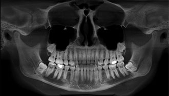 Figure 2: Panoramic radiograph of a 20-year-old woman with impacted third molars.
Ethical approval for this study was obtained from Semmelweis University. A panoramic radiograph (Fig. 2) and cone beam computed tomography (CBCT) scans of a fully dentate 20-year-old woman with impacted third molars were retrieved from the database of the authors’ clinic. The criteria for selection of this case were impaction of the mandibular third molar teeth and lack of metallic restorations in the scanned region, to limit radiographic artifacts. Data from the CBCT scans were used to build 3-dimensional patient-specific models of the mandible by means of FEA. The radiographic density in the CBCT scans was used to assign individual mechanical parameters to each element in terms of Hounsfield units (HU). A value of 0 HU was defined as the radiodensity of distilled water at standard temperature and pressure, and the radiodensity of air at standard temperature and pressure was –1000 HU.
Data Acquisition
Preoperative data for the patient were acquired with a CBCT scanner (i-CAT, Xoran Technologies, Ann Arbor, MI) with 0.3-mm voxel resolution, which was designed especially for dental and maxillofacial applications.
Modelling
Two meshes, a surface mesh and a volumetric mesh, are necessary to produce the FEA model. Converted CBCT data were imported to a visualization program called Mimics (Materialise, Leuven, Belgium) to generate an outline of the mandible, which resulted in a smooth-surface triangle mesh that was ready for further processing. Fig. 3 shows the differences between the surface generated directly from the CBCT scans, shown in brown, and the remeshed surface generated by the Mimics software, shown in green.
Meshing
The ANSYS software package (ANSYS Inc., Southpointe, PA) was used to generate the tetrahedral volumetric mesh from the triangle surface mesh of the Mimics program. There were minimal geometric modifications with this step. The numeric values describing the mandibular FEA model are displayed in Table 1.
Assignment of Mechanical Parameters
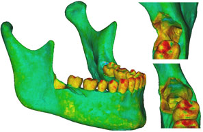
The mechanical parameters were assigned once the volumetric mesh was completed. The linear elastic modulus, also called Young’s modulus, was based on the bony radiodensity (HU) and the apparent bone density (ρapp), with the Poisson coefficient set to 0.3. A colour-coded model showing the radiodensity distribution on its surface is presented in Fig. 4a, and Fig. 4b shows the relationship between colour and radiodensity.
Virtual Removal of the Third Molar
Three models were created from the initial model. Case 1 was the negative control, representing the intact preoperative mandibular model with the impacted third molars still in place. No surgical modifications were made to this model. Case 2 was the positive control, with the impacted right third molar extracted, but no cortical bone removed. Case 3 represented the virtually simulated removal of the right impacted third molar and associated cortical bone, mainly around the crown of the tooth and at the lateral cortical wall in the area of the external oblique ridge (Fig. 5).
Boundary Conditions
Each of the 3 cases was evaluated twice, with loading of the ipsilateral and contralateral first molars, for a total of 6 simulations. The boundary condition protocol used Mimics to apply muscle traction and bony support in each simulation (Table 2; Fig. 6).
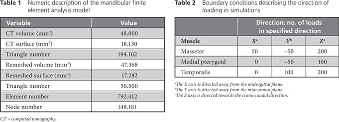
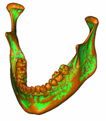 Figure 3: Three-dimensional model of the patient’s mandible. Reddish brown areas represent the primary surface, based on data from cone beam computed tomography; green areas represent surface remeshing by the Mimics software.
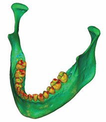 Figure 4a: A density map of the initial model was formed by adding the volumetric mesh to the model shown in Figure 3.
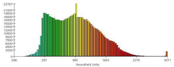
Figure 4b: Spectrum relating specific colours to radiodensity (in Hounsfield units), to aid in interpreting the model shown in Figure 4a. Areas in the model that are shown in red (e.g., cusp tips of the teeth) are those with the highest radiodensity (3000 HU). Areas in the model that are shown in light blue are those with the lowest radiodensity (0 HU). The vertical scale refers to the number of elements of each colour that were recorded in the meshed mandible.
 |
 |
|
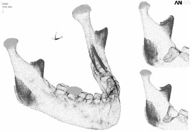
Figure 5: Finite element model of the patient’s mandible after removal of the mandibular right third molar, the pericoronal bone and bone of the lateral cortical wall of the socket in the region of the external oblique ridge. On the right side of the figure appear enlarged views of the sockets and defects left by removal of the third molar. |
Figure 6: Boundary conditions for the three cases with ipsilateral loading of the first molar. In case 1 (large mandible on the left), the third molar is still in place. In case 2 (partial mandible, top right), only the right third molar has been removed, without removal of the cortical bone. In case 3 (partial mandible, bottom right), the right third molar has been removed, along with the necessary cortical bone, mainly around the crown of the tooth and at the lateral cortical wall in the area of the external oblique ridge. |
Results
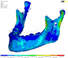
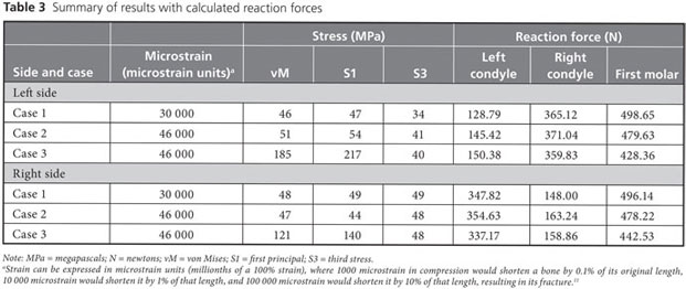
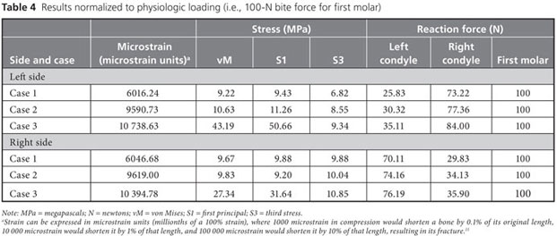
Strain, von Mises stress, first principal and third stress were evaluated using the models shown in Figs. 7–9, which present the most commonly visualized von Mises stresses, along with the results of loading of the ipsilateral first molar for cases 2 and 3. Reaction forces were calculated after all simulations in the Z-axis (craniocaudal) direction (Table 3). The results were then normalized to a 100-N, unilateral bite-loading of the first molar to reflect regular daily masticatory loading (Table 4). The modelling showed that the surgical procedure involving the external oblique ridge resulted in the greatest stress during normal clenching. The peak stress occurred at the site of removal of the third molar, during contralateral loading of the mandible.
 |
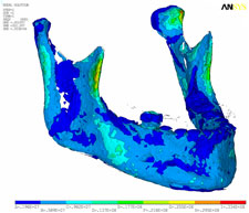 |
| Figure 7: Three-dimensional model of case 1, showing von Mises stress isosurfaces with ipsilateral loading of the first molar. In this case, the third molar remains in place. |
Figure 8: Three-dimensional model of case 2, showing von Mises stress isosurfaces with ipsilateral loading of the first molar. In this case, the right third molar has been extracted, but the cortical bone has not been removed. |
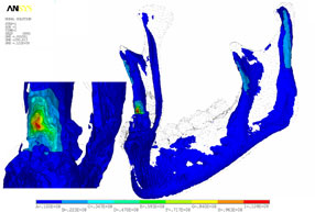
Figure 9: Three-dimensional model of case 3, with von Mises stress isosurfaces with ipsilateral loading of the first molar. In this case, the right third molar has been removed, along with the necessary cortical bone, mainly around the crown of the tooth and at the lateral cortical wall in the area of the external oblique ridge. At left appears a magnified cross-section of the surgical site, showing the effects of loading (green to red colours).
Discussion
Removal of a mandibular third molar may, in certain situations, weaken the mandible. The FEA models developed in this study showed that the external oblique ridge on each side was the location where stress was concentrated. The mandibular third molars are usually situated close to this ridge. In some cases, removal of impacted third molars may require removal of more bone than in others, and there are a variety of approaches to determining how much bone should be removed. Given the high mechanical stress associated with normal loading on the external oblique ridge, there is a possibility that the mandible will fracture during or after the procedure if large quantities of bone are removed.
The possibility of iatrogenic fracture depends on a number of factors, such as the magnitude, direction and surface area of the impacted tooth.6 Mandibular anatomy, mass and bone density also affect the patient’s susceptibility to iatrogenic fracture.6,12-14 Previous studies have confirmed that the risk of mandibular angle fractures is increased in the presence of impacted third molars.6,13,15-22 Some authors have reported that the position of the impacted third molars was associated with the frequency of mandibular fractures,14,23 but this association was not observed in other studies.17,24-26
In this study, CBCT scans of a 20-year-old woman were used to build 3-dimensional FEA models of virtual removal of the third molar. These models were then tested with loading of the ipsilateral and contralateral first molars. The following observations were noted. First, during normal chewing, the external oblique ridge is a physiologic load-bearing site. Stress accumulates in the cortical wall below its superficial layers, and this cortical wall should therefore be preserved if possible. The medial cortical walls around the region of the mandible close to the third molars do not exhibit stress shearing under regular chewing conditions. Second, if a substantial portion of the external oblique ridge is removed, as in case 3, then loading of the ipsilateral first molar results in increases in peak stress of over 100%, whereas loading of the contralateral first molar results in increases in peak stress of more than 200%.
The finding that, after removal of the third molar, contralateral biting elicits about 50% more stress than ipsilateral biting may alert the clinician to the need to modify postoperative instructions for patients to prevent excessive mandibular loading (e.g., by recommending a soft diet). FEA can also help to identify high-risk patients. Although not within the scope of this particular study, the authors have reported elsewhere that FEA can be used to predict an increased risk of mandibular fracture in elderly patients.27
The FEA results reported here suggest that sparing the external oblique ridge is desirable to maximize the tolerance of the mandible to loading. Certain scenarios may cause the practitioner to reconsider the approach to removal of the third molar, as in the case of a chronically symptomatic, deeply impacted mandibular third molar tooth in an elderly patient. Experienced practitioners may consider alternatives to removal of the external oblique ridge, such as tooth division,28 mandibular osteotomy29 and elective coronectomy, purposely leaving the roots of the impacted third molar behind.30,31
The FEA simulations of removal of the third molar described here resulted in predictions about the consequences of postoperative loading once the tooth is removed, depending on the amount of bone removed. Future studies using this FEA method could analyze the effect of partial, full bony, mesioangular, distoangular or horizontal impaction on the risk of predicted iatrogenic fracture.6,15,17,24-26 The effect of harvesting large pieces of bone graft material from the external oblique ridge and ramus of the mandible could also be evaluated preoperatively using FEA.
In the future, osteotomy designs and rigid fixation devices could be tested with FEA-generated models. In the area of tissue engineering32 and reconstruction with bone grafting or with bone substitutes,33 the load-bearing capacity of a particular bone graft or scaffold used to replace a major segment of the mandible could be predicted before its clinical use. This information might have important applications in designing future loading protocols of scaffolds, in selecting the appropriate scaffold material or in designing the shape of the scaffold, to balance the loading capacity of the particular biomaterial with the predicted clinical loading requirements of the mandibular segment that it must replace. FEA provides a new platform to make such clinically relevant predictions.
The FEA method presented in this report, which used data acquired from CBCT scans, is applicable to many specific questions during surgical planning and postoperative review, and relatively easy-to-use programs are available for this type of modelling. Future simplifications of this method and its evolution into a more user-friendly modality for dentistry may facilitate the use of FEA in the preoperative analysis of particular surgical sites. The results of FEA could then be used to predict the risk of iatrogenic fracture, thus providing dentists with more information to help in case selection and management of risk.
THE AUTHORS
|
|
Dr. Szűcs is an assistant professor in the department of oral and maxillofacial surgery and dentistry, faculty of dentistry, Semmelweis University, Budapest, Hungary. |
|
|
Dr. Bujtár is a resident in the department of oral and maxillofacial surgery and dentistry, department of oral diagnostics, faculty of dentistry, Semmelweis University, Budapest, Hungary. |
|
|
Dr. Sándor is professor and head of oral and maxillofacial surgery, University of Toronto, coordinator of pediatric oral and maxillofacial surgery, The Hospital for Sick Children and Bloorview Kids Rehab, Toronto, Ontario; professor of tissue engineering, Regea Institute for Regenerative Medicine, University of Tampere, Tampere, Finland; docent, University of Oulu, Oulu, Finland. |
|
|
Dr. Barbarás is professor and head, department of oral and maxillofacial surgery and dentistry, faculty of dentistry, Semmelweis University, Budapest, Hungary. |
Correspondence to: Dr. George K.B. Sándor, The Hospital for Sick Children, S-525, 555 University Ave., Toronto, ON M5G 1X8.
The authors have no declared financial interests.
This article has been peer reviewed.
References
- Strang G, Fix G. An analysis of the finite element method. Englewood Cliffs (NJ): Prentice-Hall; 1973.
- Frost HM. A 2003 update of bone physiology and Wolff’s Law for clinicians. Angle Orthod. 2004;74(1):3-15.
- Barron RP, Kainulainen VT, Gusenbauer AW, Hollenberg R, Sándor GK. Fracture of glenoid fossa and traumatic dislocation of mandibular condyle into middle cranial fossa. Oral Surg Oral Med Oral Pathol Oral Radiol Endod. 2002; 93(6):640-2.
- Coletti D, Ord RA. Treatment rationale for pathological fractures of the mandible: a series of 44 fractures. Int J Oral Maxillofac Surg. 2008;37(3):215-22. Epub 2007 Nov 26.
- Kainulainen VT, Lindholm TC, Sándor GK. Reconstruction of an extremely resorbed mandible by the “tent pole” procedure. Suom Hammaslääk (Finn Dent J). 2003;12(12):591-7.
- Meisami T, Sojat A, Sándor GK, Lawrence HP, Clokie CM. Impacted third molars and risks of angle fracture. Int J Oral Maxillofac Surg. 2002;31(2):140-4.
- Brown DH, Evans AW, Sándor GK. Hyperbaric oxygen therapy in the management of osteoradionecrosis of the mandible. Adv Otorhinolaryngol. 1998;54:14-32.
- Lam DK, Sándor GK, Holmes HI, Evans AW, Clokie CM. A review of bisphosphonate-associated osteonecrosis of the jaws and its management. J Can Dent Assoc. 2007;73(5):417-22.
- Khan AA, Sándor GK, Dore E, Morrison AD, Alsahli M, Amin F, et al. Canadian Association of Oral and Maxillofacial Surgeons. Canadian consensus practice guidelines for bisphosphonate associated osteonecrosis of the jaws. J Rheumatol. 2008;35(7):1-7. Epub 2008 Jun 1. Erratum in J Rheumatol. 2008;35(10):2084. J Rheumatol. 2008;35(8):1688.
- Algahtani M, Alqudah M, AlShehri S, Binahmed A, Sándor GK. Pathologic fracture of the mandible caused by metastatic follicular thyroid carcinoma. J Can Dent Assoc. 2009;75(6):457-60.
- Frost HM. Wolff's law to the Utah paradigm: insights about bone physiology and its clinical applications. Anat Rec. 2001;262(4):398-419.
- Cruz M, Wassall T, Toledo EM, da Silva Barra LP, Cruz S. Finite element stress analysis of dental prosthesis supported by straight and angled implants. Int J Oral Maxillofac Implants. 2009;24(3):391-403.
- Lee JT, Dodson TB. The effect of mandibular third molar presence and position on the risk of an angle fracture. J Oral Maxillofac Surg. 2000;58(4):394-8.
- Weiss L. Static loading of the mandible. Oral Surg Oral Med Oral Pathol. 1965;19:253-62.
- Safdar N, Meechan JG. Relationship between fractures of the mandibular angle and the presence and state of eruption of the lower third molar. Oral Surg Oral Med Oral Pathol Oral Radiol Endod. 1995;79(6):680-4.
- Tevepaugh DB, Dodson TB. Are mandibular third molars a risk factor for angle fractures? J Oral Maxillofac Surg. 1995;53(6):646-9.
- Wolujewicz MA. Fractures of the mandible involving impacted third molar tooth: an analysis of 47 cases. Br J Oral Surg. 1980;18(2):125-31.
- Halmos DR, Ellis E 3rd, Dodson TB. Mandibular third molars and angle fractures. J Oral Maxillofac Surg. 2004;62(9):1076-81.
- Lee JT, Dodson TB. The effect of mandibular third molar presence and position on the risk of an angle fracture. J Oral Maxillofac Surg. 2000;58(4):394-8.
- Kober C, Sader R, Thiele H, Bauer HJ, Zeilhofer HF, Hoffmann KH, et al. Stress analysis of the human mandible in standard trauma situations with numerical simulation. Mund Kiefer Gesichtschir. 2001;5(2):114-9. German.
- Takada H, Abe S, Tamatsu Y, Mitarashi S, Saka H, Ide Y. Three-dimensional bone microstructures of the mandibular angle using micro-CT and finite element analysis: relationship between partially impacted mandibular third molars and angle fractures. Dent Traumatol. 2006;22(1):18-24.
- Neal DC, Wagner WF, Alpert B. Morbidity associated with teeth in the line of mandibular fractures. J Oral Surg. 1978;36(11):859-62.
- Fuselier JC, Ellis EE 3rd, Dodson TB. Do mandibular third molars alter the risk of angle fracture? J Oral Maxillofac Surg. 2002;60(5):514-8.
- Ma’aita J, Alwrikat A. Is the mandibular third molar a risk factor for mandibular angle fracture? Oral Surg Oral Med Oral Pathol Oral Radiol Endod. 2000;89(2):143-6.
- Seymour RA, Meechan JG, Blair GS. An investigation into post-operative pain after third molar surgery under local analgesia. Br J Oral Maxillofac Surg. 1985;23(6):410-8.
- Ugboko VI, Oginni FO, Owotade FJ. An investigation into the relationship between mandibular third molars and angle fractures in Nigerians. Br J Oral Maxillofac Surg. 2000;38(5):427-9.
- Bujtár P, Sándor GK, Bojtos A, Szucs A, Barabás J. Finite element analysis of the human mandible at 3 different stages of life. Oral Surg Oral Med Oral Pathol Oral Radiol Endod. 2010 May 1. [Epub ahead of print.]
- Haug RH, Abdul-Majid J, Blakey GH, White RP. Evidenced-based decision making: the third molar. Dent Clin North Am. 2009;53(1):77-96.
- Sencimen M, Varol A, Gülses A, Altug HA. Extraction of a deeply impacted lower third molar by sagittal split osteotomy. Oral Surg Oral Med Oral Pathol Oral Radiol Endod. 2009;108(5):e36-8.
- Hatano Y, Kurita K, Kuroiwa Y, Yuasa H, Ariji E. Clinical evaluations of coronectomy (intentional partial odontectomy) for mandibular third molars using dental computed tomography: a case-control study. J Oral Maxillofac Surg. 2009;67(9):1806-14.
- Leung YY, Cheung LK. Safety of coronectomy versus excision of wisdom teeth: a randomized controlled trial. Oral Surg Oral Med Oral Pathol Oral Radiol Endod. 2009;108(6):821-7. Epub 2009 Sep 26.
- Sándor GK, Suuronen R. Combining adipose-derived stem cells, resorbable scaffolds and growth factors: an overview of tissue engineering. J Can Dent Assoc. 2008;74(2):167-70.
- Tie Y, Wang DM, Ji T, Wang CT, Zhang CP. Three-dimensional finite-element analysis investigating the biomechanical effects of human mandibular reconstruction with autogenous bone grafts. J Craniomaxillofac Surg. 2006;34(5):290-8. Epub 2006 Jun 15.