
ABSTRACT
Purpose: To quantify the effect of distance on the irradiance and beam homogeneity from 4 curing lights.
Methods: Four light-emitting diode curing lights were evaluated: Fusion, Bluephase 16i, Demi and FlashLite Magna. The irradiance at the centre of the light beam (ICB) was measured at 1.0 to 9.0 mm from the emitting tip using a 3.9-mm diameter probe connected to a spectrometer. The uniformity of the beam from each curing light was characterized by means of the “top hat factor” at 2.0, 4.0, 6.0 and 8.0 mm from the emitting tip. The useful beam diameter, within which irradiance values were greater than 400 mW/cm2, was calculated. The ICB, top hat factor and useful beam diameter were compared by analysis of variance and Fisher’s protected least significant difference test at α = 0.01.
Results: At all distances, the ICB was lowest for the FlashLite Magna and highest for the Fusion. Only the Fusion maintained an ICB above 1000 mW/cm2 at the 8.0 mm distance. For distances between 2.0 and 8.0 mm, the top hat factors were similar for the Fusion and the Demi, lower for the Bluephase 16i and lowest for the FlashLite Magna.
Conclusions: Beam homogeneity, top hat factors and ICB varied significantly among the curing lights. These results indicate that deep restorations may not be adequately cured if the curing time is based on data obtained when the curing light is positioned close to the radiometer or resin. In addition, a single irradiance value cannot be used to describe the light output from a curing light.
Introduction
The light-curing times recommended by dental manufacturers are based on placing the tip end of the curing light as close as possible to the surface of the resin, but in clinical situations, this positioning is often difficult or impossible to achieve. For example, the distance between the cusp tip and the base of the interproximal box may exceed 7 mm,1-3 a distance that will significantly reduce the light intensity available for photoactivation of the resin.4,5 As a result, the manufacturer’s curing times may underestimate the times required to adequately cure the resin at the bottom of the interproximal box. To differentiate the curing effectiveness among the various curing lights, it is important to characterize curing lights away from their tip ends. In a recent issue of its Professional Products Review, the American Dental Association (ADA) found that as distance from the end of the light guide increased from 2 to 9 mm, there was a 68% reduction in irradiance for the Bluephase 16i curing light (Ivoclar-Vivadent, Amherst, NY) and a 52% reduction for the Demi curing light (Kerr Corp., Orange, CA), but only a 35% reduction for the Fusion unit (DentLight, Richardson, TX).6 The reduction observed with the Bluephase 16i unit resulted in an average irradiance below 400 mW/cm2, a value that has been proposed as the minimum useful irradiance required to adequately cure dental resins.7 However, the required irradiance for adequate curing is both shade-dependent and product-dependent and may in fact be greater than 400 mW/cm2. The depth-of-cure test for dental resins described in the International Organization for Standardization (ISO) standard 4049 for polymer-based restorative materials uses a mould with internal diameter 4 mm.8 Thus when depth of cure is being tested using the ISO test, the diameter of the beam from the curing light should be greater than this 4 mm diameter test mould, and the minimum useful irradiance from the curing light should be at least 400 mW/cm2.
Some curing lights include a light guide, and the combination of the light guide and the internal optics of the unit affects irradiance and beam homogeneity.1,4,5,9,10 Some manufacturers offer “turbo” light guides to boost the light output by delivering the power (measured in watts) from the curing light over a smaller area. In one study, with the tip of the light guide touching the resin (distance = 0 mm), a 13/8-mm turbo light guide (where 13 mm is the diameter for entrance of light and 8 mm the diameter for exit of light) increased the irradiance by 52% relative to an 8-mm standard light guide used with the same curing light.1 However, beyond 5 mm from the tip, the 8-mm standard light guide delivered greater irradiance than the 13/8-mm turbo light guide.1 The Bluephase 16i curing light includes a 13/8-mm turbo light guide, which probably accounts for the 68% reduction in irradiance at 9 mm from the light guide reported in the ADA Professional Products Review.6
In addition to affecting the light output, the design of the light guide significantly influences resin polymerization.4,10 Turbo light guides with a greater ratio between entry and exit diameters (the R value) are reportedly more efficient than standard light guides for curing resins in the first 5 mm between the tip of the light guide and the resin.4 This is to be expected since the irradiance delivered to a 4-mm diameter mould by a turbo light guide is greater in the first 5 mm.1 However, beyond 5 mm from the tip, standard light guides with a lower R value deliver a greater irradiance at the centre of the light beam and have been shown to be more effective in curing the resin. The authors of the study concluded that turbo light guides should not be used to cure resins where the tip of the light guide is not in close proximity to the resin, for example, in a Class II proximal box.4
Previous studies have included qualitative visual representations of the effect of distance on the different beam distributions from curing lights,1,6,10,11 but the challenges of quantifying the irradiance distribution as a function of distance and determining the effective beam diameter from the curing light remain. For the study appearing in its Professional Products Review, the ADA used visual evaluation of the illuminated area struck by the light beam to provide qualitative evidence of beam divergence, and the resulting loss of intensity, with increasing distance.6 The loss of intensity with increasing distance was estimated by looking at concentric circles on graph paper and noting the difference in brightness at different distances. In addition, irradiance values measured at 2 and 9 mm from the tip of the curing lights were reported. In other studies, the light output at the tip of curing lights has been shown to be inhomogeneous.11-13 This inhomogeneity in light output causes inhomogeneous polymerization across the surface of resin specimens.10,14,15
Laser beam analyzers are currently the best method for quantifying the distribution of power (i.e., determining homogeneity) within a light beam. A digital image of the beam is acquired, from which the weighted average of the power values delivered to pixels within a defined beam area can be calculated. This value, the “top hat factor,” can be used to characterize the degree of spatial10-12,16 and spectral13 uniformity of the power distribution from the curing light. When the radiant power of a cross-section of the light beam is measured and then applied to the same region within the image, beam profiler software can be used to convert the relative power at each pixel into scaled 2- and 3-dimensional images of the beam’s irradiance. If the power values are the same for all pixels, then irradiance values will be the same across the surface and the top hat factor is 1.0. The literal 3-D representation for such a circular beam takes the shape of a figurative top hat: flat on the peripheral “brim,” where no light falls, and a flat-ended cylinder representing the light beam. Values below unity indicate less uniformity in the power distribution and the 3-D beam profiles appear less like a top hat. Top hat factors ranging from 0.38 to 0.76 have been reported for various curing lights, and use of a turbo light guide on a curing light significantly reduces the top hat factor.10,12
Although beam profiling of curing lights has been performed, the irradiance distribution from curing lights has not been quantified at clinically relevant distances from the light-emitting tip. Such measurement should provide a more thorough understanding of the reasons for variation in the curing effectiveness of different curing lights used in research studies and in dental offices. The purpose of the present study was to quantify the effect of distance on irradiance at the centre of the beam (ICB), overall beam homogeneity as characterized by the top hat factor and useful beam diameter (the area where irradiance is greater than 400 mW/cm2). Calibrated irradiance distributions obtained with a digital beam profiler and a 3.9-mm diameter probe attached to a spectrometer were recorded at distances of 2.0, 4.0, 6.0, and 8.0 mm from the emitting tip of each curing light. The following 3 hypotheses were tested. At the distances examined, for 4 commercial curing lights, (1) the ICB will differ among curing lights and will decrease with increasing distance; (2) beam homogeneity, as characterized by the top hat factor, will differ among curing lights but will remain approximately constant with increasing distance; and (3) the useful beam diameter will remain above 4.0 mm at a distance of 8.0 mm from the light-emitting tip.
Materials and Methods
Curing Lights
Four LED curing lights were evaluated: Fusion, with the 450-nm emission LED chip, standard light head and focus lens; Bluephase 16i, with a turbo light guide (model 592 482 Power-Booster light probe 13/8 mm, Ivoclar-Vivadent); Demi, with a turbo light guide (model 952213 with 8-mm Curved Turbo+, Kerr Corp.); and FlashLite Magna (Discus Dental, Culver City, CA). The Fusion and FlashLite Magna units do not use light guides. The batteries in the curing lights were fully charged before use, and the units were tested in a predetermined random order.
Effect of Distance on ICB
The radiant power (mW) across a 3.9-mm diameter circle at the centre of the light beam from each curing unit was measured, in triplicate, as a function of distance, in 1.0-mm increments from 1.0 to 9.0 mm, with a 3.9-mm diameter cosine-corrected probe (CC3-UV, Ocean Optics, Dunedin, FL). A laboratory-grade spectroradiometer (USB 4000, Ocean Optics) was connected to the probe with a UV-VIS fibre optic cable. Before use, all equipment was calibrated with a National Institute of Standards and Technology (NIST; Gaithersburg, MD) traceable light source (LS-1-CAL, Ocean Optics). The probe and curing light were mounted on an optical bench to allow precise, controlled positioning. The probe was centred in the emitting beam of the curing light by means of fine adjustments in 2 dimensions with the help of 2 translation stages (NT33-487, Edmund Optics, Barrington, NJ). In all cases, the diameter of the circular CC3-UV probe (3.9 mm) was less than the overall diameter of the light beam from the curing light. The radiant power was converted to ICB by dividing the measured radiant power by the area of the probe.
Effect of Distance on Distribution of Irradiance
The distribution of irradiance of the light beam for each curing light was measured with a laser beam profiler, which has been described previously.12,13 The camera was focused on the beam image appearing on the front surface of a semitransparent diffusing screen (DG2X21500, ThorLabs, Newton, NJ). The distance between the camera lens and the screen was kept constant throughout the experiment. To measure the effect of distance from the curing light on the irradiance distribution, the emitting tip of each unit was fixed parallel to the screen at distances of 2.0, 4.0, 6.0 and 8.0 mm. Distances were measured to an accuracy of 0.1 mm by means of a long-travel linear translation stage and track (NT56-798 Techspec, Edmund Optics). The image formed on the front of the screen when the light was turned on was recorded twice on a random sequence of the predetermined distances using a beam profiler (LBA-USB-L070 with a 50-mm lens, Ophir-Spiricon, Logan, UT) interfaced to a personal computer. Before each beam was imaged, its pixel dimensions were calibrated in the plane of the front face of the optical screen closest to the curing light. This allowed precise linear measurement of the images. The system was corrected for ambient light and pixel response (using the UltraCal baseline correction algorithm [Ophir-Spiricon]), the curing light was activated, and the lens iris was adjusted to use the full dynamic range of the LBA-USB-L070 detection system without signal saturation. The camera recorded the light at 60 frames per second. This rapid image-capture time allowed for differentiation between the pulsed high and low outputs from the Demi unit.
Figure 1 shows the size of a representative Class I restoration (Fig. 1a) relative to the 3.9-mm active diameter of the CC3-UV probe (Fig. 1b), although it is recognized that cavity preparations have various shapes and dimensions. To calibrate the beam image, the radiant power at the centre of the beam was measured 5 times, with the light being repositioned between measurements, for each of 4 distances (2.0, 4.0, 6.0 and 8.0 mm) from the end of the curing light by means of the CC3-UV probe connected to the spectrometer. This central circular area on each digital image corresponded to the cross-section of the beam intercepted by the probe (Fig. 1c). The dimensions of this central circular area were entered into the Ophir-Spiricon software (LBA-USB-SCOR version 4.84), along with the sum of the relative radiant power values for all pixels of the image located within the 3.9-mm diameter region of the beam image, to produce calibrated 2-D and 3-D images of the irradiance distribution. Because the Demi unit pulses between 2 levels of irradiance, only the lower power and irradiance values were reported. Figure 2 illustrates what the 2.0-, 4.0- and 8.0-mm distances used in this study represent on a human molar tooth with a Class II cavity preparation. The 2.0- and 4.0-mm distances represented positions with the light tip in contact with the cusp tip. The 8.0-mm distance represented a position in which the light tip was 4.0 mm from the top of the resin (i.e., 4.0 mm from the cusp tip) and the top of the resin was 4.0 mm below this cusp tip.
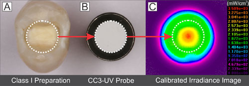 Figure 1: Comparison of diameters between a representative Class I restoration (a) and the probe (inner diameter 3.9 mm) (b). The power distribution image (c) shows a central region corresponding to the area of the probe. The radiant power measured by the probe within this region was entered into the software, which then produced a calibrated irradiance image.
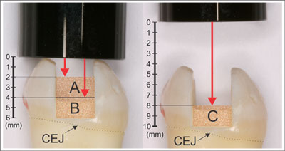 Figure 2: Distance between the tip of the curing light and the top surface of resins in a Class II cavity preparation finishing above the cementoenamel junction (CEJ). Illustrated distances from the light guide to the top of resin are 2.0 mm (a), 4.0 mm (b) and 8.0 mm (c).
Statistical Analysis
Calibrated irradiance distribution images were obtained for each curing light at distances of 2.0, 4.0, 6.0 and 8.0 mm. The top hat factors were calculated to characterize beam homogeneity at each distance. The useful beam diameter, corresponding to the cross-sectional diameter of a beam with irradiance values above 400 mW/cm2, was also calculated as a function of distance. Analysis of variance (ANOVA) was used to compare ICB, top hat factor and useful beam diameter as a function of distance for the 4 curing lights. Fisher’s protected least significant difference (PLSD) post hoc multiple-comparison test was used to compare differences in ICB, top hat factor and useful beam diameter among the curing lights at each distance. All statistical testing was performed at a preset α of 0.01 (rather than 0.05) to allow additional adjustment for the multiple comparisons at the various distances.
Results
Effect of Distance on ICB
The ICB values at various distances (Table 1, Fig. 3) differed significantly among the curing lights, as did the effect of distance on irradiance (2-factor ANOVA, p < 0.001). At distances of 1.0, 2.0, 3.0, 7.0, 8.0 and 9.0 mm, the ICB values for all of the curing lights differed significantly (Fisher’s PLSD multiple-comparison test). However, at distances of 4.0, 5.0 and 6.0 mm, there were no significant differences in ICB between the Bluephase 16i and Demi units (Table 1).
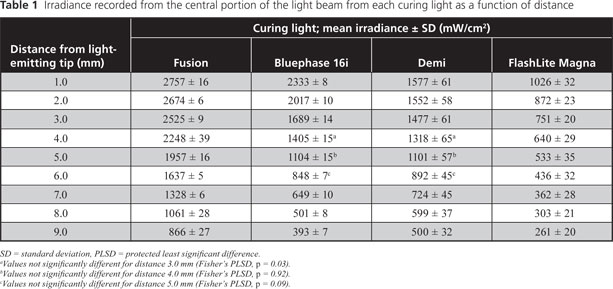
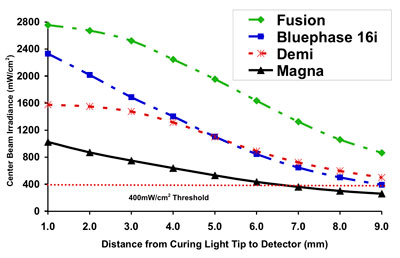 Figure 3: Centre beam irradiance as a function of distance for 4 curing lights. At a distance of 7 mm, the irradiance from the FlashLite Magna unit delivered less than 400 mW/cm2.
Effect of Distance on Distribution of Irradiance
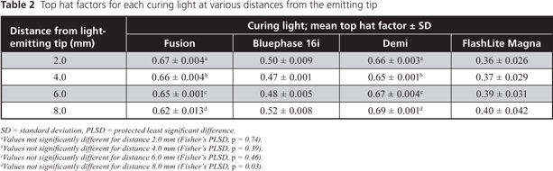
Representative 2-D and 3-D isometric colour-coded irradiance images for the 4 curing lights at distances of 2.0, 4.0 and 8.0 mm (Figs. 4 and 5) show that the FlashLite Magna had the greatest beam diameter, but its irradiance distribution was very inhomogeneous. The top hat factors reported in Table 2 were based upon the entire image for each curing light and distance. The top hat factors differed significantly among units (2-factor ANOVA; p < 0.001), and distance had no significant effect on the top hat factor (2-factor ANOVA; p = 0.19). The top hat factors were similar for the Fusion (range 0.62–0.67) and Demi (range 0.65–0.69) curing lights at all distances (Fisher’s PLSD multiple-comparison test, p = 0.07). However, beam homogeneity for the Bluephase 16i unit, as indicated by top hat factor (range 0.47–0.52), was significantly lower (p < 0.01), and the FlashLite Magna unit had the lowest (p < 0.01) top hat factors (range 0.36–0.40).
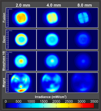 Figure 4: Two-dimensional isometric irradiance distribution images for 4 curing lights at distances of 2.0, 4.0 and 8.0 mm from the light-emitting tip. The images all have the same length and irradiance scales.
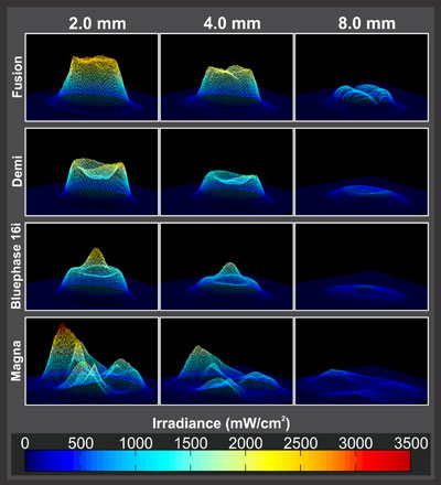 Figure 5: Three-dimensional isometric irradiance distribution images for 4 curing lights at distances of 2.0, 4.0 and 8.0 mm from the light-emitting tip. The images all have the same length and irradiance scales.
The Fusion and Demi curing lights had useful beam diameters that were similar to one another and greater than that of the Bluephase 16i at each distance (Table 3, Fig. 6). Because of high inhomogeneity, useful beam diameter could not be calculated for the FlashLite Magna curing light. In this regard, 3-D imaging (Fig. 5) illustrated regions of low irradiance and peaks with very high irradiance for this curing light. Both the unit and the distance affected the useful beam diameter, and the effect of distance differed from one curing light to another (2-factor ANOVA; p < 0.001). At the 2.0-mm distance there was no difference in useful beam distance between the Bluephase 16i and Demi units (Fisher’s PLSD multiple-comparison test; p = 0.14) (Table 3). At the 6.0- and 8.0-mm distances, the useful beam diameter for the Bluephase 16i was significantly lower (4.90 and 2.60 mm, respectively) than those of the Demi and Fusion units (all above 5.0 mm). At the 8.0-mm distance, there was no difference in useful beam diameter between the Fusion (5.31 mm) and Demi (5.36 mm) curing lights (p = 0.41). All 4 curing lights were single-peak LED units with similar spectral emissions (Fig. 7).
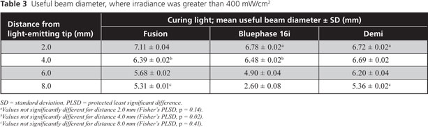
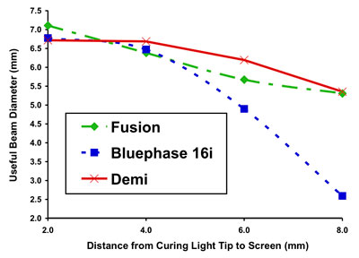 Figure 6: Useful beam diameter (where irradiance values are greater than 400 mW/cm2) as a function of distance for 3 of the curing lights. The FlashLite Magna unit lacked sufficient beam definition to assign a beam diameter and was therefore excluded from this analysis.
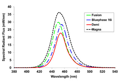 Figure 7: Spectral emission from the 4 curing lights.
Discussion
Effect of Distance on ICB
In contrast to previous studies, in which beam dispersion has been qualitatively compared by measuring the increase in diameter of a light beam projected on a screen,1,6,11 the digital beam-profiling technique used in this study quantified the irradiance distribution at 2.0, 4.0, 6.0 and 8.0 mm from the light tip. The 3.9-mm diameter probe used in this study approximates both the size of a Class I restoration and the 4-mm inner diameter of the ISO depth-of-cure mould8 (Fig. 1). Figure 2 illustrates the distances to the top surface of a resin in a Class II cavity preparation where the proximal box finishes just above the cementoenamel junction. Thus, the ICB values reported in Table 1 represent the average irradiance delivered to a resin restoration, or the ISO depth-of-cure mould, at each distance, rather than the irradiance delivered to the mouth.
The ICB delivered to a restoration varied significantly among the 4 curing lights tested in this study (Table 1 and Fig. 3). In addition, the ICB decreased with distance for all curing lights, but the rate of decrease differed (Fig. 3). As such, the first hypothesis of this study was confirmed. At distances of 1.0, 2.0, 3.0, 7.0, 8.0 and 9.0 mm from the end of the curing light, there was a significant difference in the irradiance delivered from each curing light. The decrease in irradiance with distance was attributed to beam divergence and hence to the light-gathering and focusing optics within the heads of the curing lights. The Fusion curing light delivered significantly greater ICB over all distances, ranging from 2757 ± 16 mW/cm2 at 1.0 mm to 866 ± 27 mW/cm2 at 9.0 mm from the end of the curing light (Table 1 and Fig. 3). At distances of 4.0, 5.0 and 6.0 mm, the ICB delivered by the Bluephase 16i and Demi curing lights did not differ significantly. At distances greater than 6 mm, the Demi unit delivered greater ICB than the Bluephase 16i curing light because of differing beam-dispersion characteristics (Fig. 3). The relative drop in irradiance for the Bluephase 16i was attributed to the combined effect of the unit’s internal optics and the turbo light guide on beam homogeneity. Only the Fusion curing light maintained an ICB above 1000 mW/cm2 at the 8.0-mm distance. The lowest ICB values, ranging from 1026 ± 32 mW/cm2 at 1.0 mm to 261 ± 20 mW/cm2 at 9.0 mm, were observed for the FlashLite Magna. The ICB for the Fusion and Demi curing lights remained above the 400 mW/cm2 minimum irradiance threshold7 for all distances, whereas the Bluephase 16i and FlashLite Magna units fell below this threshold at distances of about 9 and 7 mm, respectively.
Effect of Spectral Emission and Distance on Distribution of Irradiance, Top Hat Factor and Useful Beam Diameter
Using a beam profiler to record the irradiance received by each pixel and then to display a 2-D or 3-D image of the irradiance measured by each pixel yielded a precise record of the spatial variation of irradiance across the light beam. This information cannot be obtained from dental radiometers, laboratory-grade thermopiles or integrating spheres. These types of equipment all measure total radiant power, which is then divided by the area of the emitting tip to produce a single irradiance value. Although laser beam-profiling sensors that contain more pixels are available, the 307200 pixels in the charge coupled device (CCD) sensor within the beam profiler camera produced sufficiently detailed images of the irradiance distribution from the 4 dental curing lights. To minimize any potential effects of the wavelength-dependent sensitivity of the CCD sensor used in the beam profiler camera, the 4 curing lights used in this study were chosen because of their similar spectral emissions (Fig. 7).
The representative 2-D and 3-D isometric colour-coded irradiance distribution images (Figs. 4 and 5) quantitatively illustrate that the conventional single irradiance value used to describe the output from a dental curing light actually represents a wide range of irradiance values distributed across the light beam. The 2.0-, 4.0- and 8.0-mm distances used to obtain the irradiance distributions shown in Figs. 4 and 5 represent clinically relevant distances between the curing light and the top of the resin, as indicated in Fig. 2, and these distances have been confirmed with light-curing of simulated restorations in a mannequin head attached to a dental chair.17
The beam profiles differed both visually and quantitatively among the 4 curing lights (Figs. 4 and 5). The top hat factors differed significantly among units, whereas distance had no significant effect on the top hat factor, which confirmed the second hypothesis. The output from the Bluephase 16i resembled a conical distribution superimposed on a flat top (Fig. 5), and this curing light had correspondingly lower top hat factors (0.47–0.52). The FlashLite Magna did not exhibit a defined beam at any distance and had the lowest top hat factors (0.36–0.40). A previous study showed that the beam profile was directly related to the location of the LED chips in the head of this unit.12 For each curing light, the top hat factors did not vary significantly with distance, which suggests that, despite divergence of the beam, the basic shape remained the same to a distance of 8.0 mm from the light tip.
The 2004 standard of the American National Standards Institute and the ADA18 recommends that the overall minimum irradiance from a dental curing light should be at least 300 mW/cm2. However, the useful beam diameters reported in Table 3 and Fig. 7 of the current study are based on the diameter of the light beam where irradiance was greater than 400 mW/cm2. This value was chosen because it has been previously reported as the minimum useful irradiance required to adequately cure resins7 and it thus allowed determination of a useful beam diameter for each curing light at each distance. If a particular resin requires greater irradiance, then the useful beam diameter would be correspondingly smaller. At a distance of 2.0 mm, the Fusion curing light had the widest useful beam diameter (7.11 ± 0.04 mm), and there was no significant difference in useful beam diameter between the Bluephase 16i and Demi curing lights. At clinically relevant distances of 2.0 and 4.0 mm, the Fusion, Bluephase 16i and Demi had useful beam diameters between 6 and 7 mm (Fig. 6). This diameter is greater than the diameter of the Class I preparation shown in Fig. 1. Therefore, at these clinical distances, it would still be possible to deliver adequate irradiance if this light was displaced sideways by a few millimetres from the preparation. However, at distances of 6.0 and 8.0 mm, the useful beam diameter of the Bluephase 16i dropped significantly below those of the Fusion and Demi curing lights, and at 8.0 mm, the useful beam diameter of the Bluephase 16i dropped to 2.60 ± 0.08 mm. As such, the third hypothesis, that the useful beam diameter would remain above 4.0 mm at a distance of 8.0 mm from the light-emitting tip, was rejected. A useful beam diameter of 2.60 mm is less than the diameter of the Class I preparation or the ISO depth-of-cure mould (Fig. 1). As a result, with increasing distance between the tooth and the Bluephase 16i with 13/8-mm turbo light guide, the consequences of moving the curing light and of operator error would be greater. At 8.0 mm and beyond, small lateral movements would cause this curing light to deliver less than 400 mW/cm2 to the restoration.
Research and Clinical Implications and Study Limitations
The observation that beam profiles from some curing lights are not uniform has important research and clinical implications. Hand-held dental radiometers calculate irradiance on the basis of a fixed aperture, with the assumption that the curing light will deliver uniform irradiance at the emitting tip. This assumption has now been proven incorrect, and the beam profile data from the present study may help to explain the reported inaccuracy of dental radiometers.19,20 In addition, because of the inhomogeneity of the light beam, the single irradiance value that radiometers produce does not adequately describe the light output from curing lights. Since the light beams of most curing units are non-uniform and diverge with distance, irradiance as a function of distance is best evaluated by measuring the light delivered to the dimensions of a typical restoration.
This study did not evaluate all curing lights that are currently available. However, all of the units investigated here have received positive product evaluations, and 3 of them were tested in a recent ADA Professional Products Review.6 In that review, power was measured across the entire tip of the curing light, and average irradiance was calculated as the distance increased from 2 to 9 mm. Using this method of calculating irradiance, the irradiance from the Bluephase 16i decreased the most (by 68%) and that from the Fusion decreased the least (by 35%). Although a different measuring technique was used in the current study, the Bluephase 16i fitted with a turbo light guide also had the greatest drop in irradiance and the Fusion had the least drop in irradiance as distance increased from 2.0 to 9.0 mm (Table 1 and Fig. 2). According to the manufacturer, the Fusion curing light is designed with a proprietary lens system that has a wider collection angle (between 120º and 160º) than the standard lens, which typically has a collection angle below 70º. This wider collection angle is designed to minimize light loss and enables “soliton-like” propagation of the optical beam. The manufacturer’s claim that the Fusion device delivers a uniform beam of light over clinically relevant distances is supported by the results of this study. The present study also supports a previous recommendation that turbo light guides not be used to cure resins at clinically relevant distances, for example, in a Class II proximal box.4
The present study highlights that conclusions drawn from laboratory studies comparing the performance of curing lights that deliver a narrow or very inhomogeneous light beam may not be clinically relevant. This is particularly important when the irradiance received by a representatively sized restoration is measured and the useful beam diameter is calculated. Although a curing light may deliver adequate irradiance at the centre of the beam to a specimen in the laboratory, such specimens are usually measured only at the centre, the point at which they usually receive maximum irradiance. The resin will be cured less well at points other than the centre and, with some curing lights, the perimeter of a restoration may receive insufficient energy even when the centre is adequately polymerized. This issue is of concern because inadequate polymerization of resins adversely affects bond strength, the physical properties of the resin, and increases potential cytotoxicity.21-34
Although it is known that an inhomogeneous light output can cause inhomogeneous polymerization across the surface of resin specimens,10,14,15 the clinical relevance of differences in the top hat factors (Table 2) and useful beam diameters (Table 3) requires further investigation. Future studies should also examine the relationship between both spatial and spectral beam uniformity and the degree of resin polymerization across the entire surface of a restoration of clinically relevant size using a hardness mapping technique.14 In addition, when studying the effect of distance on beam uniformity, a target screen is essential. Further studies are in progress to investigate the effects of different imaging screens on the light beam profile.
Conclusions
At the distances examined, ICB varied significantly among the 4 curing lights tested. The curing lights also differed significantly in terms of beam homogeneity, as characterized by top hat factors. The top hat factors were similar for the Fusion and Demi curing lights at all distances, but were lower for the Bluephase 16i and lowest for the FlashLite Magna. At a distance of 8.0 mm, the useful beam diameter for the Bluephase 16i unit was less than 4 mm (2.60 ± 0.08 mm) and significantly lower than that of the Fusion and Demi curing lights. Finally, curing lights delivering a high irradiance exceeding 1000 mW/cm2 at their emitting tip may not adequately cure resins at the bottom of the proximal box of a deep Class II cavity preparation unless the light curing time is extended.
These results indicate that deep restorations may not be adequately cured if the curing time is based on data obtained when the curing light is positioned close to the radiometer or resin. In addition, a single irradiance value reported by a dental radiometer cannot describe the light output from a curing light.
THE AUTHORS
|
|
Dr. Price is a professor in the department of dental clinical sciences, Dalhousie University, Halifax, Nova Scotia. Email: rbprice@dal.ca |
|
|
Dr. Labrie is an associate professor in the department of physics and atmospheric science, Dalhousie University, Halifax, Nova Scotia. |
|
|
Dr. Whalen is a research associate in the department of chemistry, Dalhousie University, Halifax, Nova Scotia. |
|
|
Mr. Felix is a research assistant in the department of dental clinical sciences, Dalhousie University, Halifax, Nova Scotia. |
Acknowledgements: This study was supported by Dalhousie University, a NSERC Discovery Grant # 298326, and an unrestricted research grant to Dalhousie University from DentLight.
Correspondence to: Dr. Richard Price, Department of dental clinical sciences, Dalhousie University, Halifax, NS B3H 1W2.
The authors have no declared financial interests in any company manufacturing the types of products mentioned in this article.
This article has been peer reviewed.
References
- Price RB, Dérand T, Sedarous M, Andreou P, Loney RW. Effect of distance on the power density from two light guides. J Esthet Dent. 2000;12(6):320-7.
- Yearn JA. Factors affecting cure of visible light activated composites. Int Dent J. 1985;35(3):218-25.
- Fróes-Salgado NR, Pfeifer CS, Francci CE, Kawano Y. Influence of photoactivation protocol and light guide distance on conversion and microleakage of composite restorations. Oper Dent. 2009;34(4):408-14.
- Corciolani G, Vichi A, Davidson CL, Ferrari M. The influence of tip geometry and distance on light-curing efficacy. Oper Dent. 2008;33(3):325-31.
- Felix CA, Price RB. The effect of distance from light source on light intensity from curing lights. J Adhes Dent. 2003;5(4):283-91.
- Spectral curing lights and evolving technology. ADA Prof Prod Rev. 2009;4(4):1-12.
- Rueggeberg FA, Caughman WF, Curtis JW Jr. Effect of light intensity and exposure duration on cure of resin composite. Oper Dent. 1994;19(1):26-32.
- International Standard 4049. Dentistry — polymer-based filling, restorative and luting materials. Geneva, Switzerland: International Organization for Standardization; 2000.
- Nitta K. Effect of light guide tip diameter of LED-light curing unit on polymerization of light-cured composites. Dent Mater. 2005;21(3):217-23.
- Vandewalle KS, Roberts HW, Rueggeberg FA. Power distribution across the face of different light guides and its effect on composite surface microhardness. J Esthet Restor Dent. 2008;20(2):108-17; discussion 118.
- Vandewalle KS, Roberts HW, Andrus JL, Dunn WJ. Effect of light dispersion of LED curing lights on resin composite polymerization. J Esthet Restor Dent. 2005;17(4):244-54; discussion 254-5.
- Price RB, Rueggeberg FA, Labrie D, Felix CM. Irradiance uniformity and distribution from dental light curing units. J Esthet Restor Dent. 2010;22(2):86-101.
- Price RB, Labrie D, Rueggeberg FA, Felix CA. Irradiance differences in the violet (405 nm) and blue (460 nm) spectral ranges among dental light-curing units. J Esthet Restor Dent. 2010;22(6):363-77.
- Price RB, Fahey J, Felix CM. Knoop microhardness mapping used to compare the efficacy of LED, QTH and PAC curing lights. Oper Dent. 2010;35(1):58-68.
- Arikawa H, Kanie T, Fujii K, Takahashi H, Ban S. Effect of inhomogeneity of light from light curing units on the surface hardness of composite resin. Dent Mater J. 2008;27(1):21-8.
- LBA-USB Beam Profiler User Guide. Logan, UT: Ophir-Spiricon; 2006.
- Price RB, McLeod ME, Felix CM. Quantifying light energy delivered to a class I restoration. J Can Dent Assoc. 2010;76(2):a23.
- ANSI/ADA Specification No. 48: Visible Light Curing Units. Chicago, IL: American National Standards Institute /American Dental Association; 2004. Available: http://www.ada.org/830.aspx (accessed 2011 Jan 13).
- Roberts HW, Vandewalle KS, Berzins DW, Charlton DG. Accuracy of LED and halogen radiometers using different light sources. J Esthet Restor Dent. 2006;18(4):214-22; discussion 223-4.
- Leonard DL, Charlton DG, Hilton TJ. Effect of curing-tip diameter on the accuracy of dental radiometers. Oper Dent. 1999;24(1):31-7.
- Halvorson RH, Erickson RL, Davidson CL. An energy conversion relationship predictive of conversion profiles and depth of cure for resin-based composite. Oper Dent. 2003;28(3):307-14.
- Nomoto R. Effect of light wavelength on polymerization of light-cured resins. Dent Mater J. 1997;16(1):60-73.
- Caldas DB, de Almeida JB, Correr-Sobrinho L, Sinhoreti MA, Consani S. Influence of curing tip distance on resin composite Knoop hardness number, using three different light curing units. Oper Dent. 2003;28(3):315-20.
- Correr AB, Sinhoreti MA, Sobrinho LC, Tango RN, Schneider LF, Consani S. Effect of the increase of energy density on Knoop hardness of dental composites light-cured by conventional QTH, LED and xenon plasma arc. Braz Dent J. 2005;16(3):218-24. Epub 2006 Jan 12.
- Lohbauer U, Rahiotis C, Krämer N, Petschelt A, Eliades G. The effect of different light-curing units on fatigue behavior and degree of conversion of a resin composite. Dent Mater. 2005;21(7):608-15.
- Xu X, Sandras DA, Burgess JO. Shear bond strength with increasing light-guide distance from dentin. J Esthet Restor Dent. 2006;18(1):19-27; discussion 28.
- Kim SY, Lee IB, Cho BH, Son HH, Um CM. Curing effectiveness of a light emitting diode on dentin bonding agents. J Biomed Mater Res B Appl Biomater. 2006;77(1):164-70.
- Staudt CB, Krejci I, Mavropoulos A. Bracket bond strength dependence on light power density. J Dent. 2006;34(7):498-502. Epub 2006 Jan 18
- Ferracane JL, Mitchem JC, Condon JR, Todd R. Wear and marginal breakdown of composites with various degrees of cure. J Dent Res. 1997;76(8):1508-16.
- Vandewalle KS, Ferracane JL, Hilton TJ, Erickson RL, Sakaguchi RL. Effect of energy density on properties and marginal integrity of posterior resin composite restorations. Dent Mater. 2004;20(1):96-106.
- Moin Jan C, Nomura Y, Urabe H, Okazaki M, Shintani H. The relationship between leachability of polymerization initiator and degree of conversion of visible light-cured resin. J Biomed Mater Res. 2001;58(1):42-6.
- de Souza Costa CA, Hebling J, Hanks CT. Effects of light-curing time on the cytotoxicity of a restorative resin composite applied to an immortalized odontoblast-cell line. Oper Dent. 2003; 28(4):365-70.
- Franz A, König F, Anglmayer M, Rausch-Fan X, Gille G, Rausch WD, et al. Cytotoxic effects of packable and nonpackable dental composites. Dent Mater. 2003;19(5):382-92.
- Knezevic A, Zeljezic D, Kopjar N, Tarle Z. Cytotoxicity of composite materials polymerized with LED curing units. Oper Dent. 2008;33(1):23-30.